The practical difficulties, along with the environmental and monetary costs of obtaining and placing drainage gravel are well-known. Recognition of the inadequacies of the traditional methods and the increasing use of geotextiles as filters led to the development of drainage geocomposites. These geocomposites have been an accepted form of drainage in a range of civil engineering applications for over 25 years and are now available in a variety of forms. This document discusses how water flow rates are assessed in both drainage gravel and drainage geocomposites.
Groundwater Drainage: Geocomposites vs. Gravel
Groundwater Drainage Applications
Groundwater drainage applications are wide ranging and include vertical (e.g. drainage behind a retaining wall or basement), horizontal (e.g. drainage on a podium deck) and various sloped situations (e.g. drainage systems within landfills or ground de-watering systems). The flow capacity of a granular drainage layer depends on its size (cross sectional area), the hydraulic gradient, the permeability of the drainage medium, and, in the case of drainage geocomposites, the confining pressure.
Groundwater flow in Drainage Gravel
The defining properties specified for a granular drainage layer are its size (cross sectional area) and the permeability of the granular material.
Permeability of Granular Material
The permeability (k) of granular materials is typically measured in a laboratory and is reported as a value in m/s.
Calculating the Flow Capacity of Drainage Gravel
Using Darcy’s Law for the movement of water, the flow capacity through a granular material is given by:
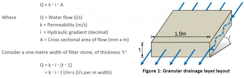
The specified permeability of filter stone typically varies from 10-1m/s to 10-4m/s and buried structures typically have hydraulic gradients of 0.01 to 1.0 (equivalent to near horizontal and vertical applications, respectively). So the maximum drainage capacity for a typical 300mm thick granular drainage layer can be anywhere in the range of 30 l/ms to 0.0003 l/ms.
Groundwater Flow in Drainage Geocomposites
What are Drainage Geocomposites?
Drainage geocomposites typically comprise a drainage core with a Polypropylene (PP) geotextile laminated to one or both sides, and are typically characterized by their core type. They are a lightweight, cost-effective and have equivalent or better drainage capacity compared to more traditional granular drainage solutions wrapped in a geotextile or encased within porous concrete.
Drainage geocomposites allow water to flow much faster than in a granular drainage media. The effective permeability of a drainage geocomposite is around 50 times that of drainage gravel due to the open void structure provided. Considering the relative densities of each material, this means that 1kg of drainage geocomposite has the same flow rate as 1T of drainage gravel (Bamforth, 2008).
How is Drainage Geocomposite Water Flow Measured?
Water flow in a drainage geocomposite is known as in-plane flow and is measured in a laboratory in accordance with EN ISO 12958 or ASTM D4716. These tests place the geocomposite under a constant pressure and measure the water flow at a constant hydraulic gradient. Multiple tests at varying pressures and hydraulic gradients can be used to build up a flow chart to understand flow behaviour in different conditions. The test result is usually reported in litres per second per metre width (l/m·s). One of the key parameters of this test is how the pressure is applied to the geocomposite. This is because when a geocomposite is installed adjacent to a deformable medium, such as soil, the geotextile may be pushed into the HDPE core which may throttle flow. The test methods allow the use of either hard or soft platens. The soft platens simulate installation in soil or similar conditions and it is important to ensure that test results that are used for design are those that best reflect the conditions on site in which the geocomposite is to be used.
Additional Benefits
As well as offering drainage performance, drainage geosynthetics also offer significant environmental, economic and safety benefits, since they are lighter and easier to install than traditional methods. The greenhouse gas emissions of a drainage geosynthetic solution is 50-90% lower than traditional solutions due to the significantly reduced mass of material required, reduced transport emissions and the quicker and easier installation. For the same reasons, the emission of harmful nitrogen oxides (NOx – mostly from diesel engines) is reduced by 70-95% (Heritage and Shercliff, 2020). The same source identifies costs are reduced by 80-95% and discusses the safety benefits from the reduced vehicle movements that are in conflict with pedestrian movements (aka exposure time).
Conclusion
As demonstrated above, drainage geocomposites can be used to replace granular drainage in almost all applications. The methods in this technical note describe the process by which a drainage gravel design can be compared with a drainage geocomposite. In addition, drainage geocomposites are better for the environment, more cost effective and safer to install compared with traditional gravel drainage. For a specific illustration for your site, contact u for a calculation based on this Technical Note.
References
ASTM D4716 / D4716M-20, Standard Test Method for Determining the (In-plane) Flow Rate per Unit Width and Hydraulic Transmissivity of a Geosynthetic Using a Constant Head, ASTM International, West Conshohocken, PA, 2020, www.astm.org
Bamforth, A. (2008) Role of Platen Hardness on Interpretation and Use of In-Plane Flow Capacity Test Results for Geosynthetics. Paper presented at the 4th European Geosynthetics Conference, Scotland, 2008.
French Standards. Geotextiles and geotextile related products – Determination of water flow capacity in their plane. NF EN ISO 12958:2020.
Koerner, R. M. (2012) Designing with Geosynthetics, 6th Edition. Indiana, United States: Xlibris